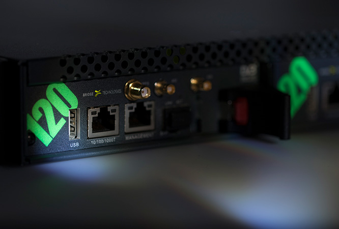
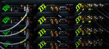
Jump to Content Open menu

VB120

VB120 EMBEDDED IP AND RF PROBE

The VB120 broadcast probe offers a cost-effective and powerful monitoring solution, covering most common signal formats found in any media operation. In particular, the VB120 is capable of monitoring IPTV multicasts, OTT/ABR streams, SRT streams as well as a whole range of RF formats. The VB120 probe hardware platform is custom designed by Bridge Technologies with the key design goals being an MTBF of at least 15 years and a power usage of less than 30 Watts for a fully populated 1RU chassis.

The VB120 probe hardware is custom-designed and built to telco-grade standards for maximum reliability. This makes the solution particularly suited for installations in remote and hard-to-get-to locations with a minimum of maintenance and where there are constraints on air conditioning, power usage and personnel. Each VB120 blade consumes less than 12W of power and is designed for an MTBF of 15 years, thus substantially reducing power consumption and air conditioning needs in installations.

The VB120 can be paired with a full set of interface blades to cover signal formats such as DVB-T/T2, DVB-S/S2/S2X, DVB-C, QAM-B, ATSC1.0, ATSC3.0, ISDB-T and ASI. Up to 13 ASI or RF transport streams can be concurrently monitored in a single 1RU chassis. The ability to continuously measure all your media services makes the VB120 invaluable for confidence monitoring, thus facilitating a more rapid network expansion. Up to 13 ASI or RF transport streams can be concurrently monitored, with options for up to 50 IP multicasts and 50 OTT/ABR streams. Streaming formats supported currently include Microsoft Smoothstream™, Apple HLS™, Adobe HDS™, MPEG-DASH and basic RTMP. 

The VB120 performs deep analysis of the broadcast signals and offers a web-based interface ideal for remote access as well as signal record and relay functionality over IP. This reduces the need to travel to remote locations when changes in the system are made or to find the reason behind alarms. 

The VB120 broadcast probe relies on a 1RU chassis for power and interface capabilities. Each chassis has 3 card bays and the VB120 controller module is typically situated in the left-most bay. There are 4 chassis variants available to suit most installation needs. 

The ACC 1RU chassis option is the most cost-efficient option and offers a single 100-240V AC PSU and 3 fans with air direction from left-to-right when viewed from the connector side.  

The EC 1RU chassis is the preferred choice for redundancy. It offers two 100-240V AC PSU units with separate power inlets, 6 fans with air direction front-to-back, chassis fan and temperature alarming as well as seamless power fail-over switching.  

The two AC models above are mirrored in corresponding –48V DC variants. These are called ECC and EC-DC, respectively. 

RF and ASI input modules

The VB120 can be bundled with up to 2 additional plug-in modules in one 1RU chassis, enabling monitoring of non-IP based signal formats such as ASI and RF. The list of supported standards includes ASI for intra head-end coaxial wiring, DVB-T/T2 terrestrial networks, DVB-C/QAM-B cable-tv networks, DVB-S/S2/S2X satellite DTH infrastructure, ATSC1.0/3.0 terrestrial distribution in the US and ISDB-T as found in terrestrial networks in Brazil and Japan. The monitoring unit is deployed on a standalone basis and accessed through its own built-in web server, or via the VBC Controller in a larger system. The openly available External Integration Interface allows for third-party management system integration such as DataMiner by Skyline Communications.

VB246 ASI Input Module

The VB246 module is designed to provide customers who require high ASI monitoring density with 6 ASI inputs operating in parallel. Monitored concurrently and with continuous ETSI TR 101 290 analysis, the VB246 is ideal for existing infrastructures in the head-end and regional edge-multiplexer/modulator/transmitter sites. Each 1RU chassis supports up to two VB246 modules for a total ASI density of 13 (the last one being local to the controller VB120/220 module). The physical interface is 6 x 75 ohm BNC Female. Each input has a matching red/green signal lock status LED on the card front. 

VB252 DVB-T/T2 terrestrial input module

The VB252 DVB-T/T2 COFDM input module (w/ 1PPS synchronizations) is ideally suited for continuously monitoring the performance of terrestrial distribution networks. Typical usage includes transmitter tower monitoring where the monitoring probe is co-hosted with the RF Exciter. Alternative usage is as a standalone off-air monitoring probe capable of receiving the signal from multiple transmitters operating in SFN in fringe coverage areas. The VB252 plug-in module supports one DVB-T/T2 COFDM RF input by default. The second input can be activated by the customer via a software licensing option. A chassis can be equipped with a VB120 probe controller that has one or two VB252 RF input cards under its control, for a maximum of 4 independent RF input ports. Full ETSI TR 101 290 analysis is performed on all active RF inputs. The Advanced RF Option adds impulse response graphing and analysis to the VB252, making it possible to check reflection conditions at the probe location. Configurable threshold limits determine when an alarm should be raised due to reflection changes in time or power. Impulse response analysis results are presented as a user-friendly graphical GUI, facilitating reflection measurement interpretation.

VB256 ISDB-T terrestrial input module

The VB256 ISDB-T input module expands Bridge Technologies’ digital terrestrial monitoring capabilities to encompass the Latin American and Japanese terrestrial markets. Supporting both ISDB-T/SBTVD-T standards, it enables customers operating in these regions to fully monitor their ISDB-T transmissions. A chassis can be equipped with a VB120 probe controller that has one or two VB256 RF input cards under its control, for a maximum of 4 independent RF input ports. Full ETSI TR 101 290 analysis is performed on all active RF inputs.

VB258 terrestrial/cable RF

The VB258 offers 4 independent RF inputs that allow for monitoring and analysis of RF streams as found in terrestrial and cable architectures, with the system facilitating one RF input by default, and the other three by license activation. Formats supported are DVB-T/T2, ATSC1.0/ATSC3.0, DVB-C, QAM-B and ISDB-T. Up to two VB258 modules can be placed into a single chassis for 8 independent RF inputs. Each RF input is further capable of round-robin operation to allow for monitoring of a full frequency raster, as typically found in DVB-C/QAM-B cable networks. The VB258 complements the VB120, offering key monitoring features such as TR 101 290 analysis, IP multicast monitoring, HLS/M-DASH monitoring, TS recording, RF analysis and SRT relay operations. This latter feature – SRT relay operation – is of particular interest since it allows for the conversion of any received RF stream into an IP/UDP stream, which is then made available via the SRT standard. SRT (Secure Reliable Transport) allows for reliable UDP streaming across Internet-type media, and through this it is possible to gain central access to streams that would otherwise be hard to access.

VB262 digital cable

The VB262 Dual QAM/8VSB input option offers monitoring of cable TV signals as found in ITU-T J.83 Annex A/B/C QAM networks and 8VSB signals found in ATSC1.0 terrestrial networks. The VB262 plug-in module supports one RF input by default. The second input can be activated by the customer via a software licensing option. A chassis can be equipped with a VB120 probe controller that has one or two VB262 RF input cards under its control, for a maximum of 4 independent RF input ports. Full ETSI TR 101 290 analysis is performed on all active RF inputs.

VB272 Satellite input module

The VB272 input card offers monitoring and analysis of QPSK/8/16/32APSK signals found in DVB-S/S2 satellite Contribution and DTH networks. Each VB272 module has one RF input activated by default. The second input is activated through a license key option. Each chassis can be equipped with a VB120 probe controller and up to two VB272 input cards under its control, for a total of up to 4 independent RF inputs. Full ETSI TR 101 290 analysis is performed on all active DVB-S/S2 inputs. Each RF input has a built-in antenna 13V/18V drive and 22kHz tone control. DisceqC 1.0 switching is supported.

Redundancy switching modules

The option for redundancy switching on the VB120 enables 2:1 A/B-style redundancy switching to take place based on alarms from the full TR 101 290 specification and not only basic parameters such as signal loss or carrier sense. Two supporting modules – the VB243 and VB273 – are available, offering relay switching on ASI-type signals and L-band or IF satellite style signals respectively. Applications include main/backup redundancy switching at terrestrial TV towers or at satellite uplink facilities. The switching blades listed contain bi-stable relays, making them capable of maintaining the switching state even without any power applied to the system.

VB243 ASI Intelligent redundancy switch

The VB243 provides full dual-path redundancy for ASI signals with autonomous operation and deep signal analysis on both signal paths for the ultimate switching decision making. Front panel controls with illuminated buttons offer local override control and a clear visual indication of the active switching path. The redundancy switch offers three distinct modes of operation making it suitable for any real-life operational challenges: automatic, manual and SuperLocal.

VB273 Intelligent Redundancy Switch

The VB273 Intelligent Redundancy Switch also provides full dual-path redundancy autonomous operation and deep signal analysis on both signal paths, but operates in the context of Satellite operations. The solution is ideal for providing fast and robust redundancy switching for permanently installed satellite up-links or in outside broadcast systems. As with the VB243, front panel controls with illuminated buttons offer local override control and a clear visual indication of the active switching path, and also operates on an automatic, manual and SuperLocal basis, as required - making it suitable for any real-life operational challenges. The VB273 comes in two factory-ordered variants, depending on whether the input signal is 70MHz IF or L-band.

QoE & QoS content monitoring

In the connected media consumption landscape, there exists a vast amount of data that needs to be understood – and acted upon. These volumes of data need exceptional analytical tools if the data is to make sense, and the VB120 hardware probe provides exactly this: in-depth analysis for detailed understanding of data for error, jitter, dropped packets, latency and low throughput analysis, producing hard, empirical QoE & QoS data – without the false positives.

QoE Content monitoring

What matters to audiences is their ultimate user experience, not the technicalities of network performance. As such, unlike many monitoring solutions in the market, the solutions from BRIDGE Technologies place a deliberate focus on establishing the end user’s Quality of Experience (QoE). QoE functionality involves audio/video content extraction and processing techniques such as MOS average, VMAF scoring, freeze-frame/color-freeze error, audio level and stereo phase detection and real-time audio loudness monitoring. This functionality is mainly reserved for the VB330/VB220 and software/appliance-based products in the portfolio and not the VB120 embedded solution. However, the VB120 also has some QoE functionality in the form of a thumbs mosaic available for all streams extracted as well as a straightforward thumbs freeze-frame detection algorithm included. 

QoS monitoring at the IP and TS level

Regardless of whether the video in question is multicast, unicast (OTT/ABR), carried over IP or ASI, through a CDN or directly, and irrespective of compression and TS standard employed, the VB120 incorporates tools necessary to monitor specific attributes of each type of cast – with insight generated at the IP, TS and Content level. Quality of Service (QoS) monitoring represents the backbone of a comprehensive monitoring solution – understanding network performance along the full media chain; from point-of-origin, through the CDN and across the final mile: uptime, downtime, error rates, bandwidth, latency, profile switching alignment – QoS ensures that network movement is occurring within established parameters, and provides the data that engineers need to identify problem points and engage in strategic improvements.

Patented Visualisation

The VB120 contains unique visualisation technologies such as the MediaWindow and the microETR. The MediaWindow allows the operator to gain key knowledge about the carriage quality of the media multicasts over time selectable time intervals. Color-coded graphs give an intuitive feel for how well the signal behaves in terms of QoS parameters such as packet loss and packet jitter. The microETR deals with transport streams and allows for the real-time alarm state of hundreds of media streams to be viewed in a single view. This allows for faults to be spotted and pinpointed in seconds. Together these techniques result in a graphical user interface that is packed with essential information, yet intuitive and easy to read.

MediaWindow™

Multicast Monitoring

An extensive range of multicast parameters can be displayed at-a-glance, pertaining to IP, TS, Ethernet, RTP and FEC. Associated thumbnails are also displayed, which can be expanded to produce a more frequently updated single image – or alternatively, display error information in cases where thumbnails cannot be obtained. For each multicast stream, peak and aggregate values for an extensive range of signal, bitrate and packet data are all displayed, up to a duration of four days, customizable according to the user’s priorities. The detection and joining of multicasts into the probe is also facilitated in an intuitive and simple-to-achieve manner. Both IPv4 and IPv6 are supported.

Traffic - Microbitrate Bursting

A common problem in any large enterprise or public network infrastructure is the occurrence of packet bursts. These typically happens due to congestion points and resulting packet queues accumulating inside the Ethernet switches and IP routers making up the network. When the network is used to transport video these aberrations can have a particular adverse effect. This unique functionality allows the network engineer to detect the amount of micro bursting and also trend this over time to spot patterns otherwise very difficult to pinpoint. Microbitrate burst monitoring is available on the VB120 through a software license option called Advanced Ethernet Option that in addition also offers PCAP capture and multicast VoD monitoring.

SRT contribution and cloud monitoring

Bridge Technologies is a proud member of the SRT alliance, and recognizes the value that this robust quality, low latency, open-source video streaming protocol presents to the industry. The VB120 can receive up to 4 SRT streams and forward them to the main monitoring framework for further analysis. This includes MediaWindow visualisation, TR 101 290 analysis, content capture and thumbnail mosaic. Key parameters such as round-time and lost-packets are displayed. The VB120 can also send out any two media streams currently being monitored by the probe as an SRT-formatted stream. This capability is typically used for ad-hoc transport of content across an IP network for remote live viewing or recording. SRT support is a standard feature on the VB120.

Customisable Alarming and visualization

The VB120 does not simply display in-the-moment network data to network engineers, but allows for the full customization of alarms, thresholds and parameters across nearly every measurement metric available. This allows engineers to prioritise issues and manage their network in the way that best suits their needs. Alarm customization is easy and intuitive, and the readouts simple to understand, and capacity for alarms of different types is maintained independently with each group maintaining no bearing on the capacity of another; this includes 100 Full Service Monitoring and Microbitrate (FSM), 2500 OTT alarms, 10000 ETR290 alarms, and 2500 System alarms. A further 20000 alarm entries can be stored in non-volatile memory by employing the FLASH32-OPT. This is particularly useful in remote applications where logging all alarms is important but at the same time the management network connectivity is not always reliable. 

Testing according to ETR290

TR 101 290 testing ensures that the interoperability parameters of TS streams – including intervals, section gaps and tables – are all met. The VB120 has a capacity of 50 concurrent ETR290 engines. It groups errors into Priority 1, 2 and 3 errors, but further allows for the user to fully customize alarming and adapt the thresholds of various ETR290 components.

Gold TS Protection™

Gold TS protection represents an upgrade on the established TR 101 290 standard, including testing for critical conditions that are not covered under ETR290 testing, whilst also making fault tracking much faster, more accurate and secure. It includes identification of failures – all of which are vital real-world quality assurance elements that have direct effect on end-user subscribers. For operators of digital media services Gold TS saves significant time in setup and diagnosis. Easier setup is facilitated through the use of a much faster calibration process than that associated with ETR290, by capturing an ideal transport stream and setting this as a reference value. Easier diagnosis is achieved by reducing the huge volumes of data that technical staff are required to wade through, instead replacing this with quick flagging and clear presentation of the error condition with deviation from protection values highlighted, and side-by-side presentation of correct values. The result is a reduction in time- to-resolve errors of a factor between 10 and 15: meaning Op-Ex is reduced by allowing maintenance staff to effectively monitor larger numbers of streams, whilst quality and reliability of service delivered to subscribers is significantly enhanced.

IAT - Histogram

The Inter Arrival Time (IAT) histogram gives you a view of how well the timing of the media multicast received is over time. It shows an accumulated count of the number of IAT measurements that fall within each presented bin interval. Vertical green lines indicate the maximum and minimum IAT values observed. The user can customize the scales.

Return Data Path

With the advent of fully duplex technologies as IP transportation, new features for allowing remote access to regional ingress signals are vital. Return Data Path allows the operator to record video locally on the probe or re-route live video monitored by the probe to a central location for decryption and further analysis. Recording is initiated either directly by the operator or automatically based on pre-defined alarm trigger criteria. RDP reduces the need for truck rolls and otherwise necessary on-site visits, by making available centrally signals that are normally only available locally. RDP™ also facilitates a simpler descrambling process for scrambled signals, by transporting the stream to the NOC, head-end or anywhere else for visual monitoring. Currently supported protocols for remote relay include UDP and RTP uni/multicast and Secure Reliable Transport (SRT).

OTT/ABR monitoring

The VB120 incorporate powerful OTT/ABR analysis engines for gaining insight into any adaptive bitrate video distribution, particularly in VoD and Live. Supported formats include HLS, MPEG-DASH, CMAF,  SmoothStream, HDS, basic RTMP and Shoutcast for radio. Each OTT Engine operates autonomously and only requires knowledge of the URL from which the media is being fetched. The OTT Engine then parses the manifest file provided by the origin or edge-server, extract the different profiles served, validates syntax, checks chunk counters and then does the same for the individual profiles. Support for AES-based decryption is included as well as an innovative method for customizing the expected format of the manifest files received.  

Thumbnails

As with the multicast and RF/ASI monitoring functionality, thumbnails for every OTT channel are displayed if successfully descrambled or available in the clear. These thumbnails can then be clicked through to for each profile, along with associated data (actual bitrate, expected bitrate, etc) of each profile. Thumbnail update rate is dependent on compression standard and resolution and can be adjusted by the user.

Origin server CDN monitoring

he maximum number of OTT/ABR streams for the VB120 platform is 50 and is available through software licenses that can be activated by the user. There is no practical limit on the number of bandwidth profiles supported within one OTT/ABR stream.

SCTE-104 and SCTE-35 Marker Monitoring

The capability of monitoring ad inserts is of particular importance to safeguard the revenue flow of any media operation relying on commercials as an income. Advertising breaks are typically signalled using either the SCTE-104 (uncompressed) or SCTE-35 (compressed) standards. These standards describe messages – or events – that flow together with the main signal telling downstream equipment when to switch in and out advertising content. By adopting the additional SCTE35-OPT, the VB120 can support for monitoring SCTE-104 carried inside ST.2038 or SCTE-35 directly in all the IP and ASI/RF transport streams monitored as all the activated ABR/OTT unicast streams. Events are logged internally in the probe and also visualised in the content timeline view. Relevant alarms are generated in case of erroneous syntax or mismatching timing.

Security — Tacacs+

The VB120 uses best practices from the IT industry to ensure continued operational stability and the highest level of protection against attack. The VB120 ensures continued operational stability using HTTPS to secure and encrypt the communications channels, thus practically eliminating the possibility of man-in-the-middle attached. This provides broadcast facilities with the ability to architect and use IP broadcast capabilities with confidence and ease.

Technical specifications

KEY FEATURES VB120 MONITOR PROBE

  • 10/100/1000-T RJ45 Management port with Link and Activity LED indicators
  • 10/100/1000-T RJ45 video port with Link and Activity LED indicators
  • SFP gigE video port with Link and Activity LED indicators
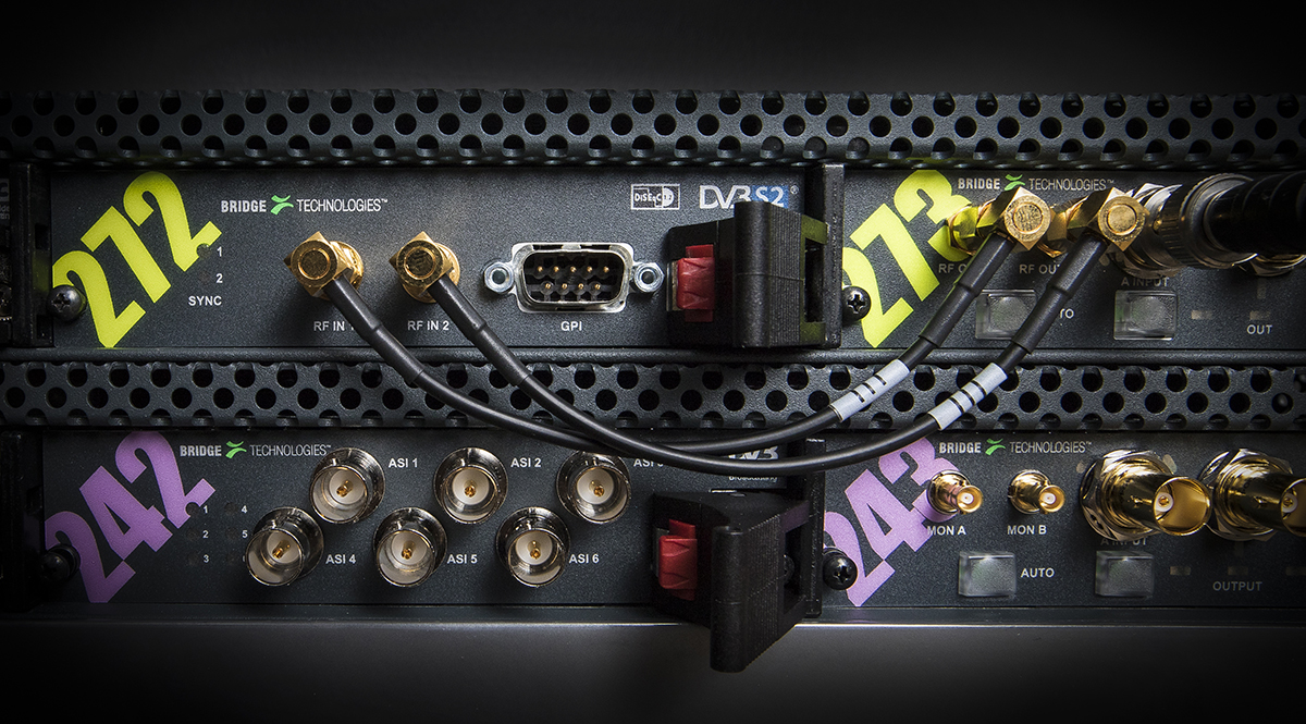
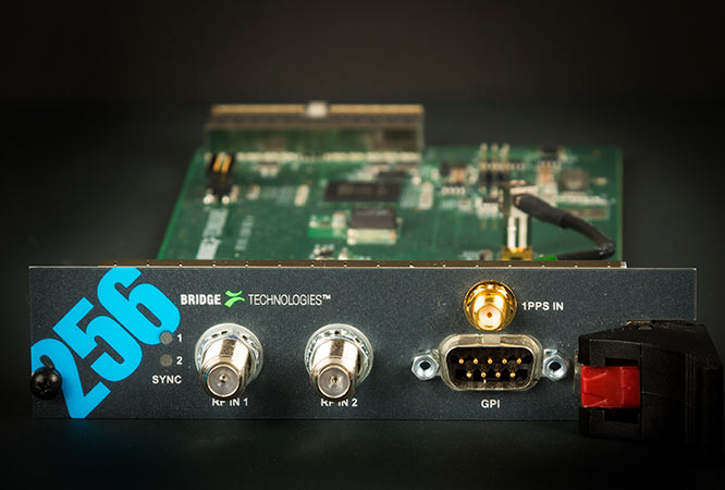
  • 75 ohm HD-BNC ASI input port with TS SYNC LED indicator
  • 75 ohm HD-BNC ASI output port for monitoring purposes
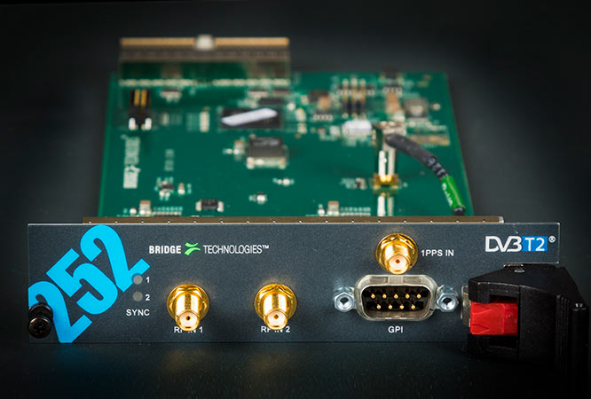
  • 50 ohm SMA female 1PPS input port for GPS synchronisation
  • USB Type-A connector for initial setup
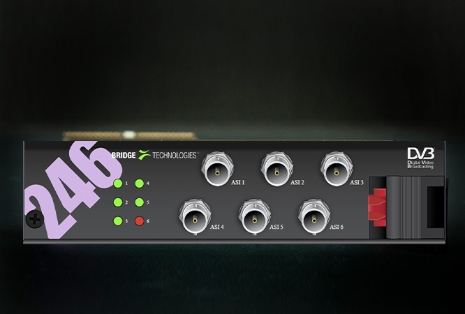
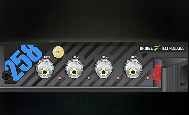
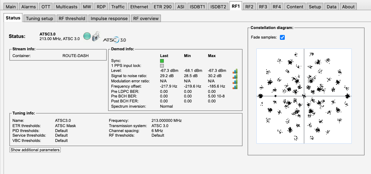
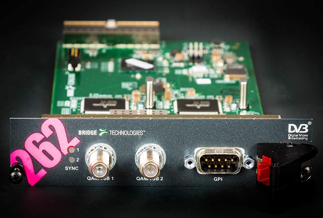
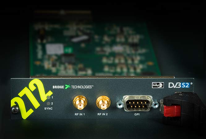
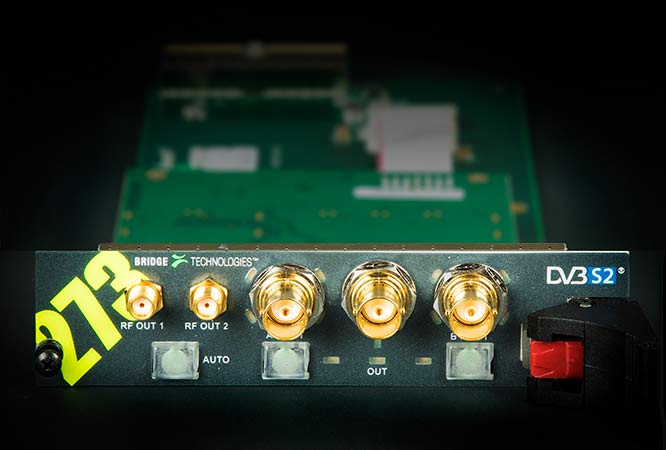
  • Expansion blades available for common formats such as DVB-S/S2/S2X, DVB-C/QAM-B, DVB-T/T2, ATSC1.0/ATSC3.0, ASI 
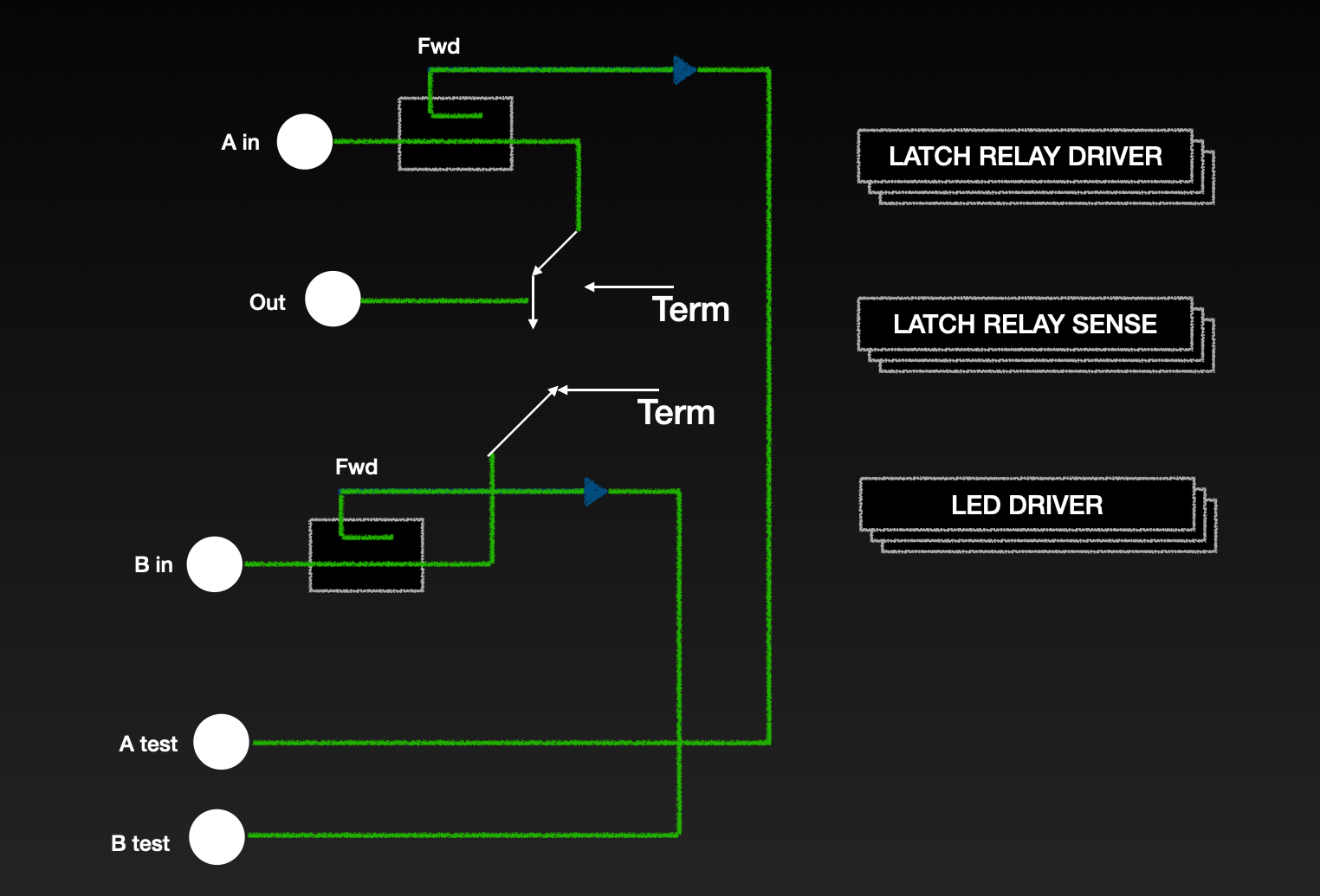
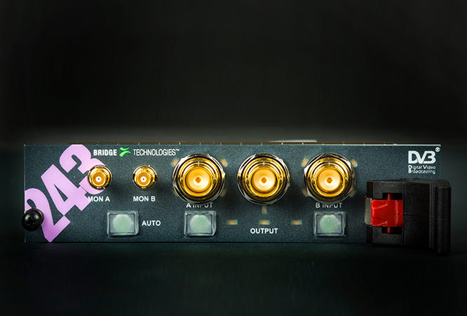
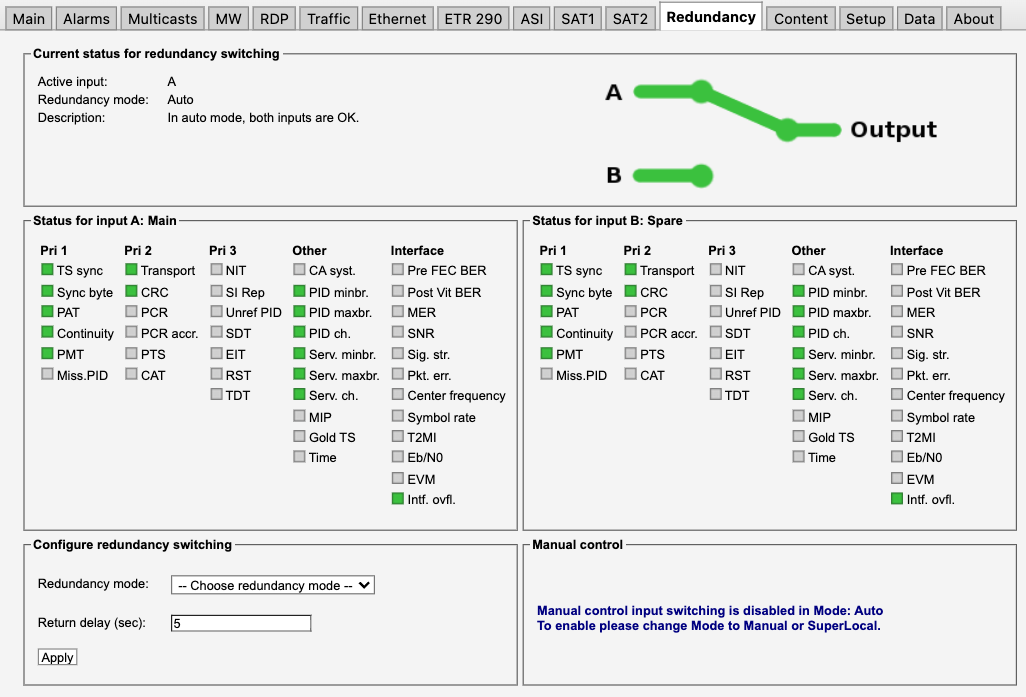
  • 2:1 redundancy switching expansion blades available suitable for terrestrial and satellite systems 
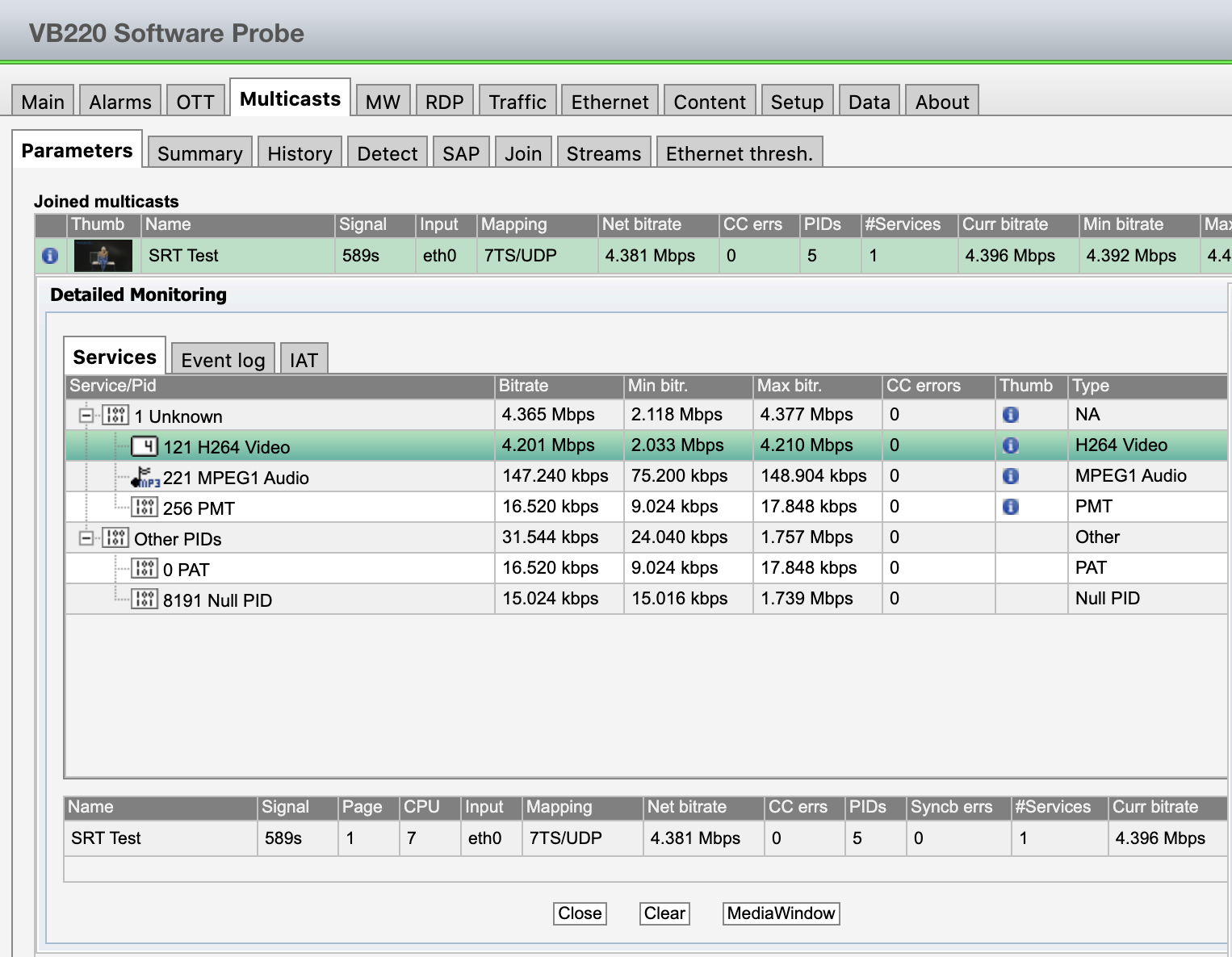
  • Parallel and continuous monitoring of up to 260 IP unicasts/multicasts according to ETSI TS 102 034
  • Support for up to 200 concurrent TR 101 290 analysis engines on IP multicast 
  • Support for monitoring of up to 250 HLS/M-DASH OTT Streams 
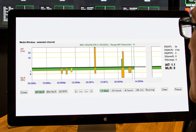
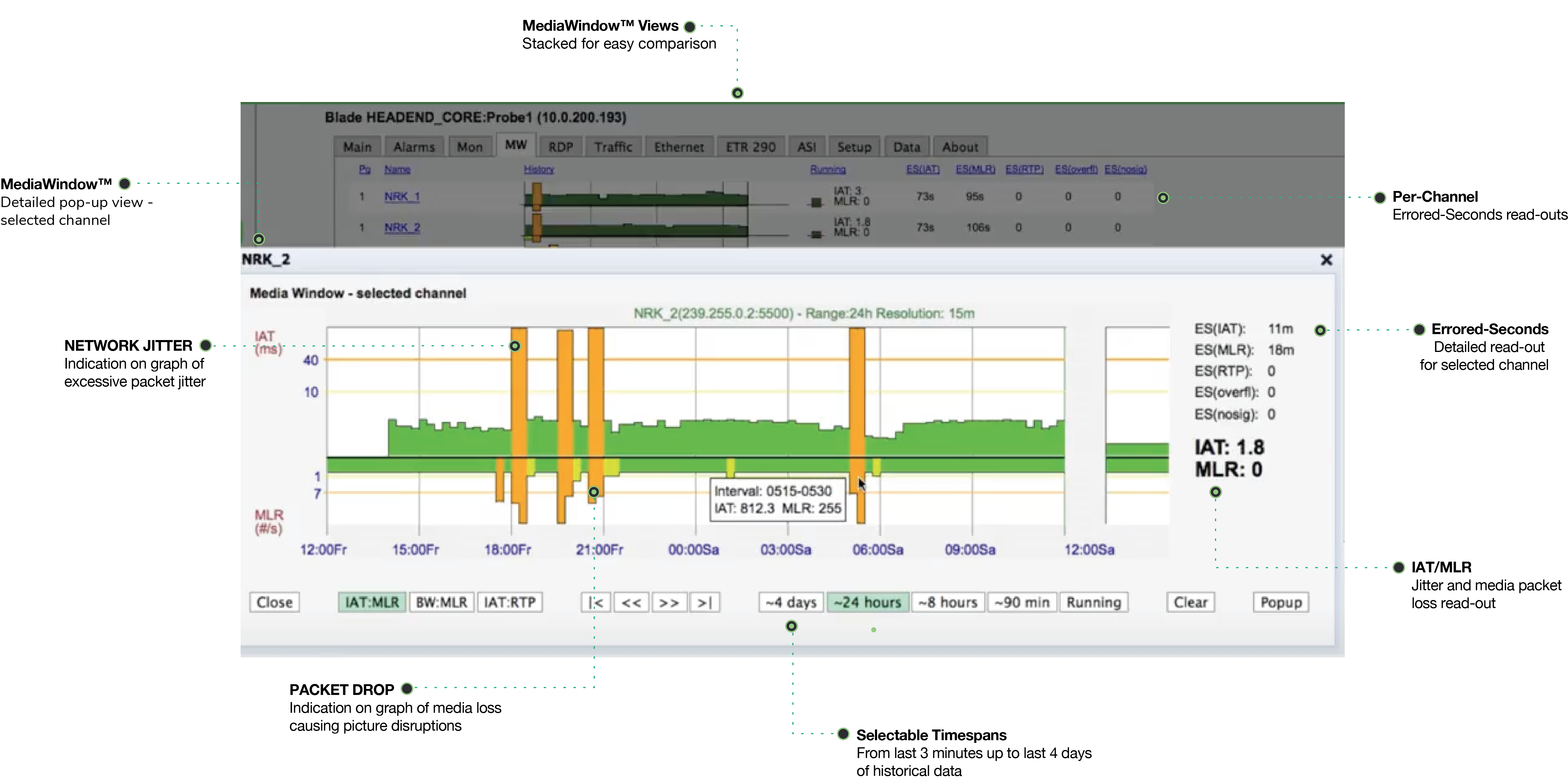
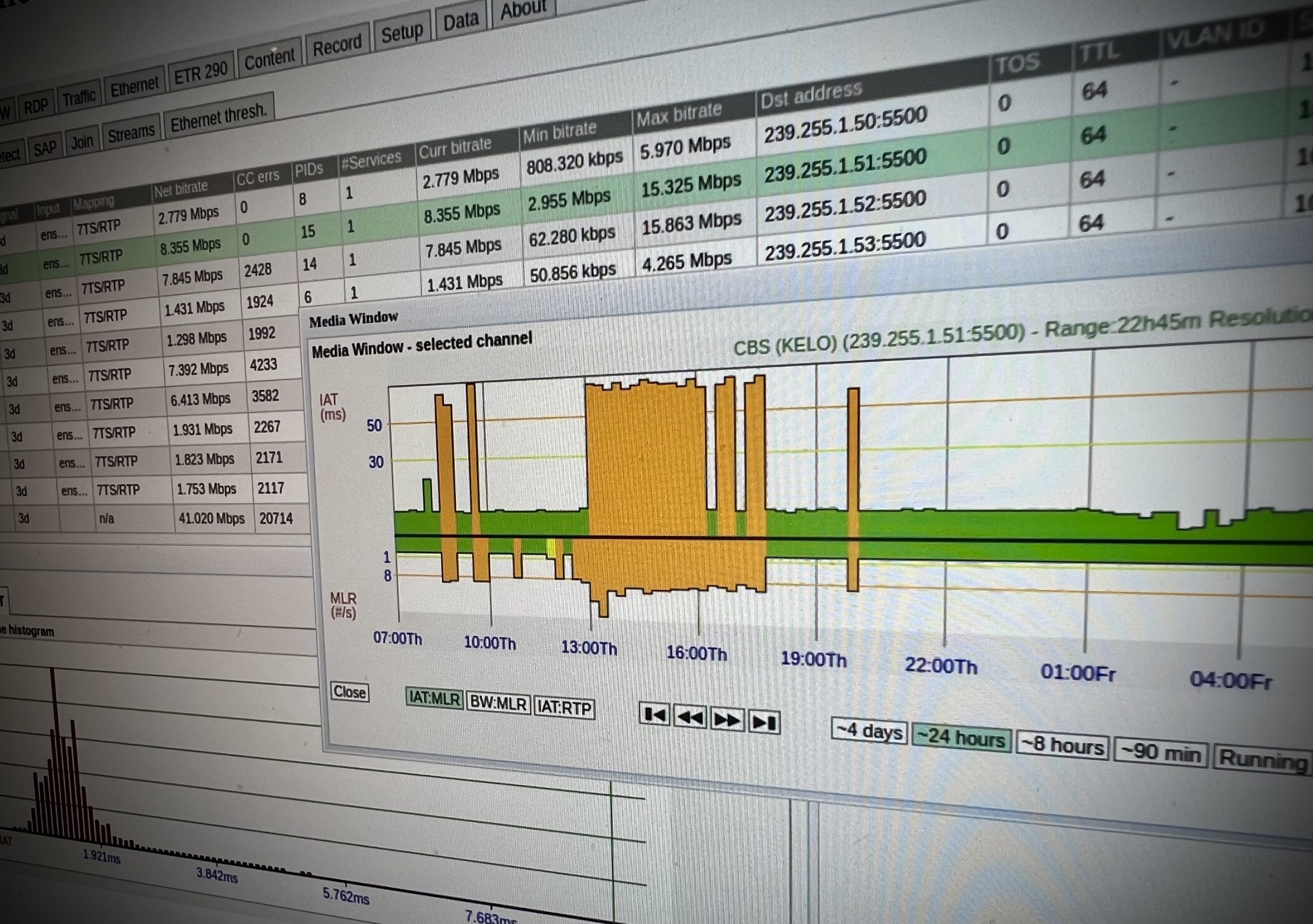
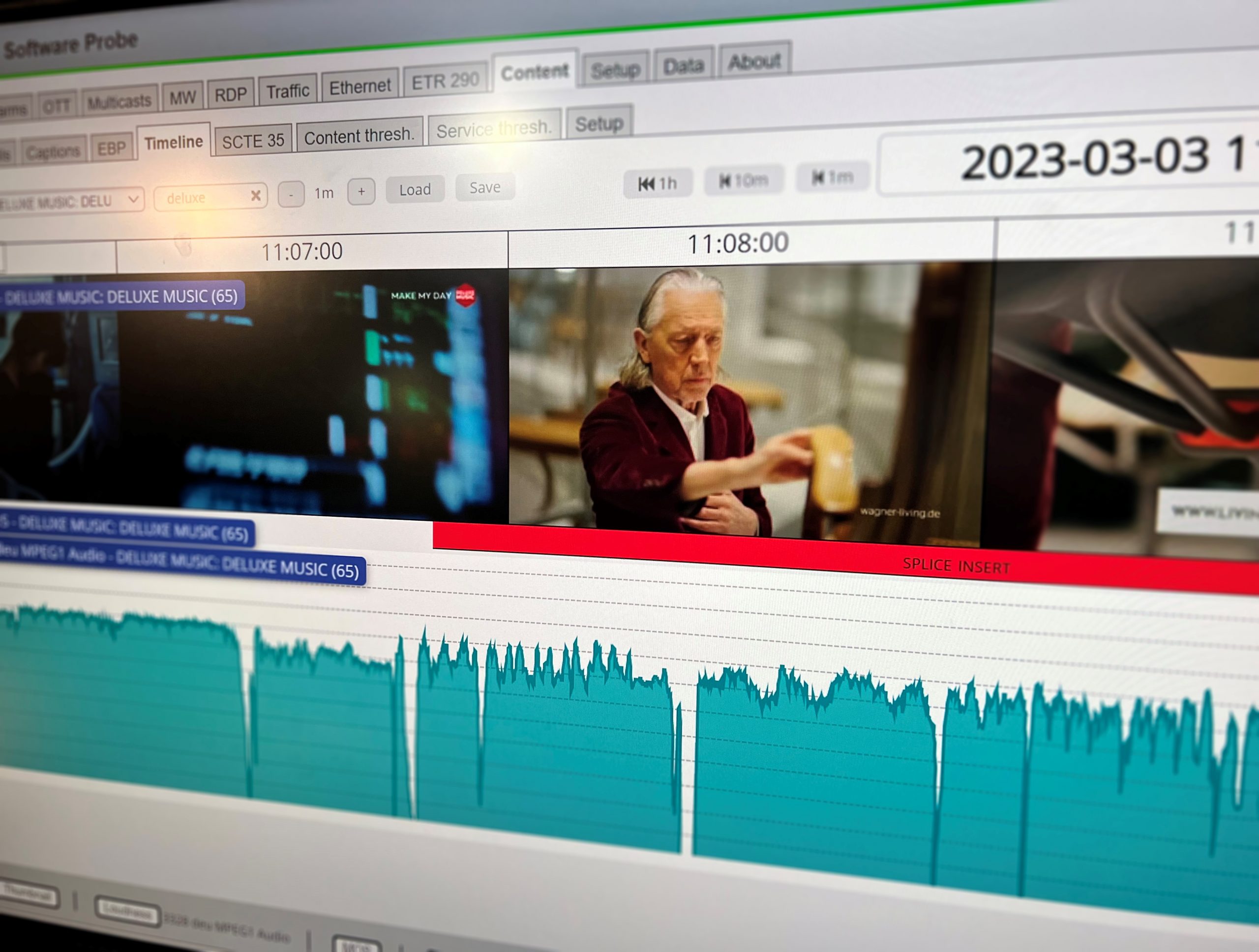
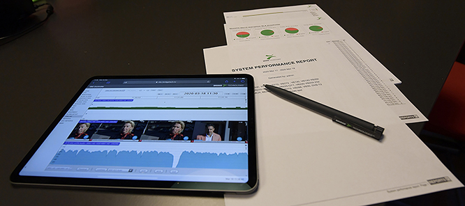
  • MediaWindow™ visualisation technology for trending packet loss, bandwidth and jitter over up to 4 days
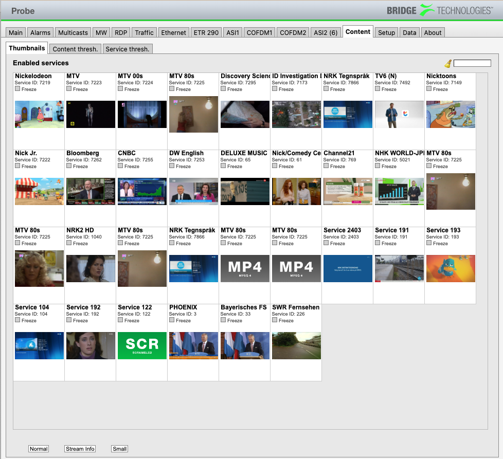
  • Thumbnail decoding of uni/multicast IP transport streams with audio bars and metadata
  • Full Service Monitoring of up to 10 network devices via built-in ICMP and HTTP query agents
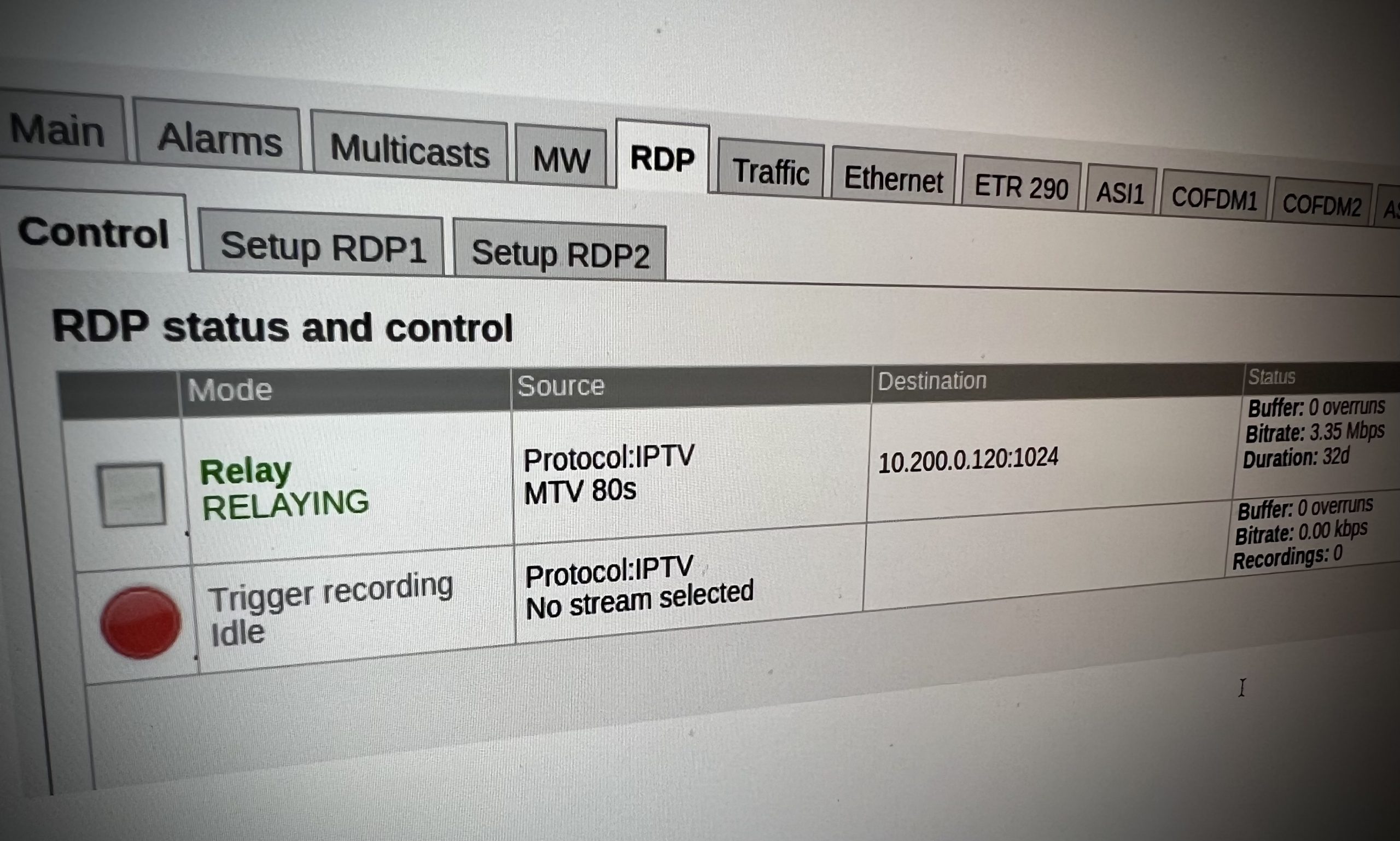
  • Framework called RDP for relaying any IP or RF/ASI stream monitored to a different IP destination for further analysis 
  • Support for Secure Reliable Transport (SRT) for transmitting any two streams monitored as part of RDP framework 
  • Support for Secure Reliable Transport (SRT) for receiving and monitoring up to four streams 
  • Functionality for record 200MB of the whole or parts of any transport stream monitored (RDP framework)
  • Automatic record trigger based on up to 3 configured alarm criteria with pre fill in order to catch fault
  • Framework for passive detection of present multicast/unicast streams on the interfaces 
  • Framework for actively scanning preconfigured multicast ranges for signal presence 
  • Support for Session Announcement Protocol (SAP) for convenient multicast channel list distribution
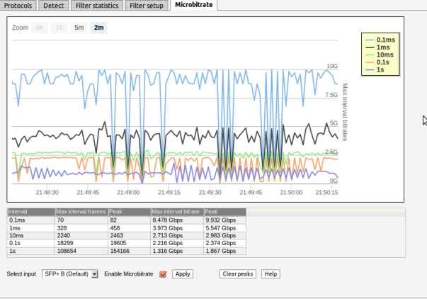
  • Protocol hierarchy view with bandwidth and packet count statistics for video interface
  • Support for ST 2022-7 redundant streams monitoring with differential timing view and accumulated lost packet’s view 
  • IGMPv2/v3 protocol logging and analysis framework
  • Flexible template based alarming system to allow custom configuration of what parameters result in an alarm being generated on a per-TS leve
  • History graphs from last 4 days of NoSignal, CC-errors, RTP-drops, RTP-duplicates, RTP-Out-of-order, Total interface bitrate, Monitored bitrate, Ethernet CRC frame errors
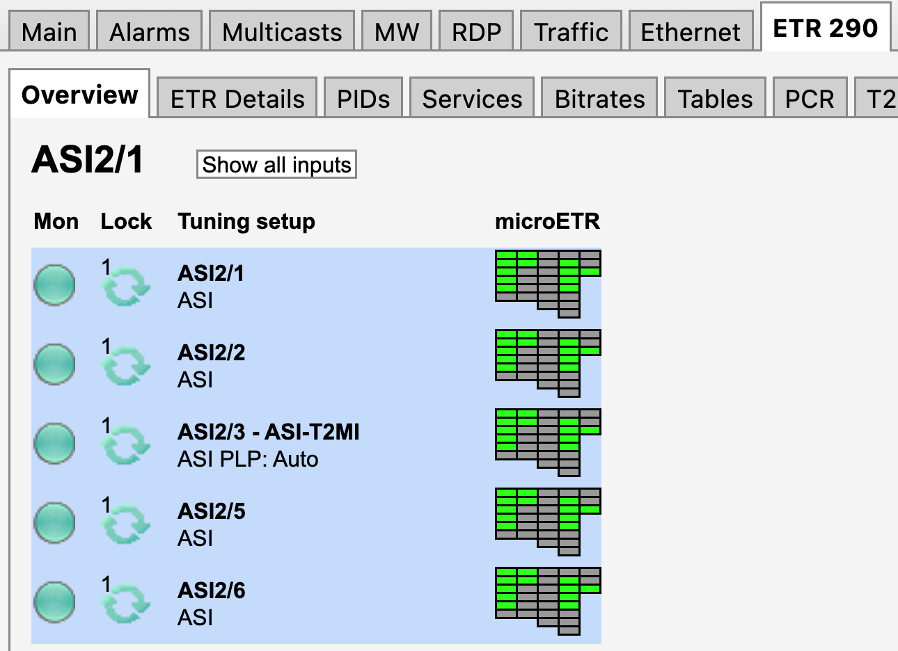
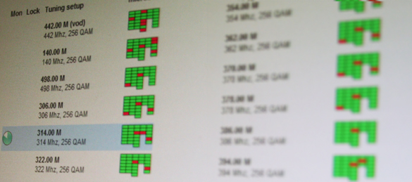
  • One ETR290 engine automatically activated per RF/ASI input port on interface modules
  • IEEE 802.1Q VLAN tagging support
  • Microsoft mediaRoom X-bit RTP header extension support
  • Alarm on changes to TOS/DSCP and TTL for detection of changes in network prioritization
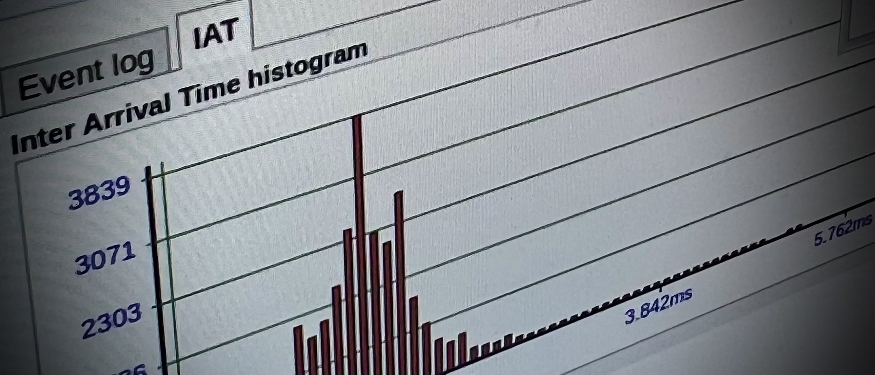
  • Time loss distance measurements according to RFC3357
  • Alarm forwarding to 3rd party systems via SNMP TRAP via up to 3 unique destinations
  • NTP client time synchronization support according to RFC2030
  • DHCP client support on management and video ports according to RFC2131
  • Easy web-based software and license upgrade
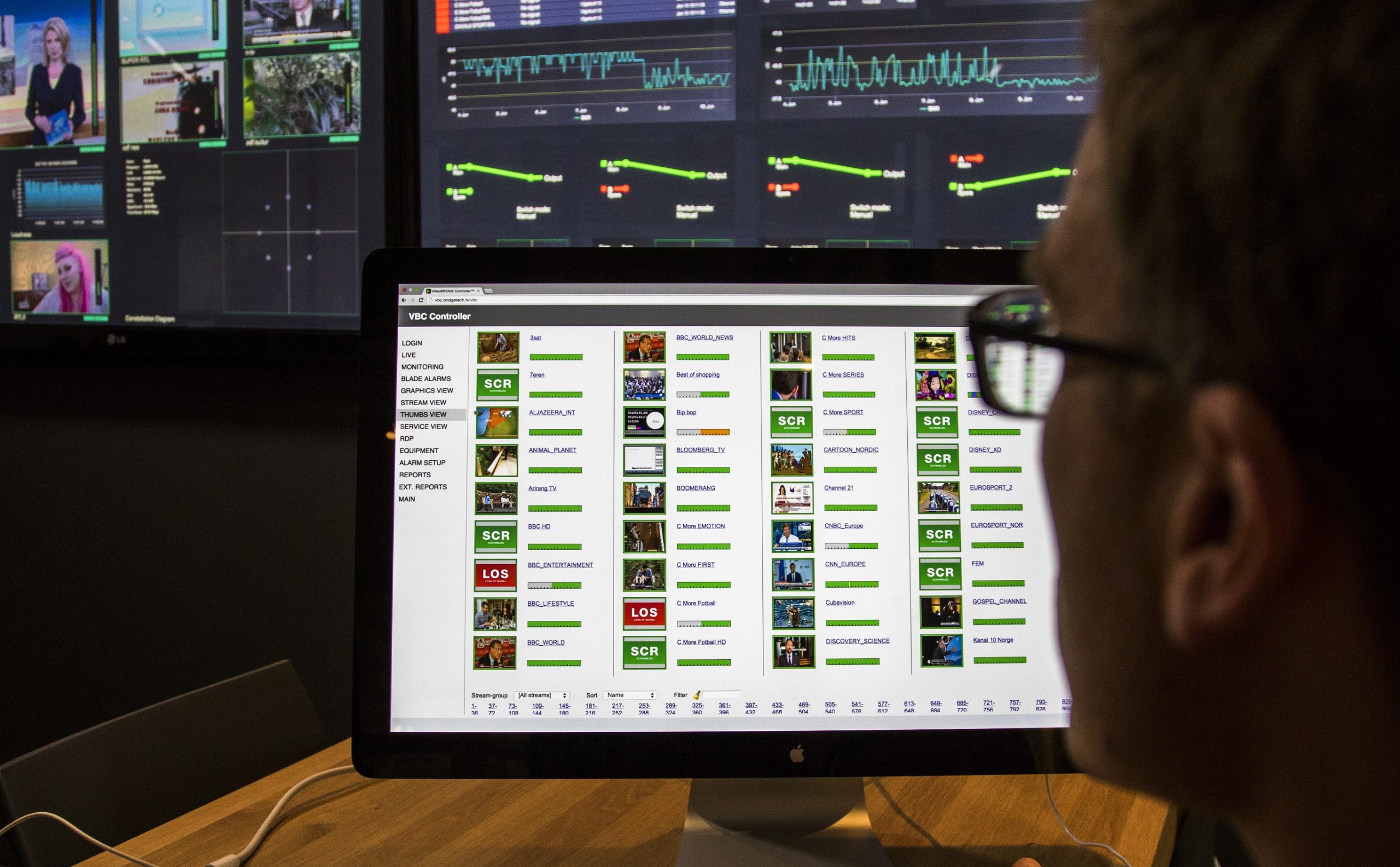
  • Tightly integrated with VideoBRIDGE Controller (VBC)
  • XML-based configuration save and retrieval via web
  • Powerful and openly available XML-based External Integratoin Interface (Eii) for 3rd party integration
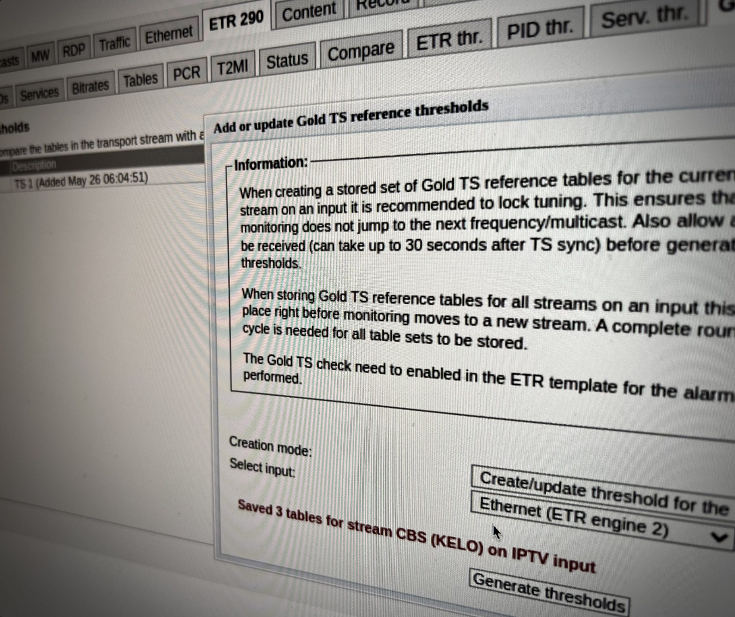
  • Gold TS Protection™
  • Condensed mosaic thumbnail view of all services monitored

FUNCTIONALITY

  • Enable continuous TR 101 290 monitoring and analysis on IP multicasts in convenient granular steps of 1 and 25
  • Full real-time ETSI TR 101 290 alarming and analysis (Pri 1, 2, 3), one transport stream per input monitored in parallel
  • Expand multicast stream coverage further by activating round-robin functionality for each ETSI TR 101 290 analysis engine
  • TR 101 290 alarming and analysis (Pri 1, 2, 3) on the local ASI input on the controller module activated
  • Gold TS Protection included 
  • Conforms to both DVB and ATSC specifications
  • Table and descriptor parsing of PSI/SI and PSIP presented as table summary and full table breakdown (including hex dump)
  • EPG analysis (EIT p/f and schedule)
  • PCR histogram visualisation
  • Unique PCR-versus-PTS analysis functionality for timing synchronization verification
  • Bitrate monitoring and alarming (TS, service and PID level)
  • Monitoring of vital CA parameters
  • Compare view for comparison of transport streams and services across different interfaces
  • Sophisticated threshold template system for detailed alarm handling control at transport stream, service and component level
  • Scheduled alarm masking

VB120 Embedded/Hardware

  • Standard 19″ 1RU rack-mount 
  • W x H x D: 483 x 43 x 400 mm 
  • Weight: 4.2 kg fully populated 
  • Operating temperature: 0℃ to 45℃
  • Storage temperature: -20℃ to 70℃
  • Operating humidity: 5% to 95% non-condensing
  • Input voltage: 100-240 VAC +/- 10% 50/60Hz
  • Maximum power requirement fully populated single-PSU chassis: 50W / 110 – 220VAC / 50-60 Hz
  • Maximum power requirement fully populated dual-PSU chassis: 75W / 110 – 220V AC / 50-60 Hz
  • Power consumption: 12W per blade
  • 10/100/1000-T management RJ-45
  • 10/100/1000-T Video RJ-45
  • SFP Video
  • Initial setup: USB Type-A
  • HD-BNC 75ohm female ASI input
  • HD-BNC 75ohm female ASI output loop through
  • SMA female 50ohm 1PPS GPS input

VB246 ASI INPUT INTERFACE MODULE

  • 6-input ASI module
  • One mode: Constant monitoring of all 6 ASI inputs
  • Higher stream count and higher performance
  • Compatible with all chassis options (ACC, EC, DCC, EC-DC)
  • 6 x 75 ohm female BNC inputs
  • 6 red/green LED indicators
  • Support for continuous analysis of all 6 x ASI inputs
  • Supports DVB-ASI according to EN 50083-9, Annex B
  • Supports Burst mode, Spread mode and legacy M2S
  • Supports 188-byte packet format and 204-byte packet format

VB252: DVB-T/T2 TERRESTRIAL RF INPUT MODULE

  • Choice between 50 ohm female SMA (VB252-SMA) or 75 ohm female F-type connectors (VB252)
  • 50 ohm female SMA 1-pulse-per-second GPS input for SFN Drift measurements
  • 9-pin D-Type male connector for relay alarm indication
  • One red/green LED TS sync indicator per RF input
  • Supports DVB-T EN 300-744 and DVB-T2 EN-302-755
  • Frequency range 43 – 1002 MHz
  • Symbol rate range 0.7 – 7.2 Msym/s
  • All versions of DVB-T2 supported: 1.1.1, 1.2.1 and 1.3.1
  • DVB-T2 Base and DVB-T2 Lite profiles supported (1.3.1)
  • Channel bandwidth: 1.7 (T2-Lite only), 5, 6, 7 and 8 MHz
  • Round-robin capability across multiple PLPs within one frequency
  • Capable of monitoring the following RF parameters:
  • Channel power RF level
  • Modulation Error Rate MER(PLP)
  • Signal to Noise Ratio SNR
  • Center Frequency Offset
  • Spectrum sense
  • 1PPS Input Lock
  • Pre Viterbi BER (DVB-T)
  • Pre Reed Solomon BER (DVB-T)
  • Pre LDPC BER (DVB-T2)
  • Pre BCH BER (DVB-T2)
  • Post BCH FER (DVB-T2)
  • Packet Error Rate
  • LDPC Iterations count
  • DVB-T SFN Drift monitoring for measuring absolute transmission time of mega frame
  • DVB-T2 SFN Drift monitoring by measuring timing of T2MI frame versus received RF super frame
  • Channel impulse Response diagram
  • Constellation diagram
  • Extract and display over 30 signalled DVB-T2 L1 Pre information parameters
  • Extract and display over 20 signalled DVB-T2 L1 PLP information parameters
  • Extract and display 9 signalled DVB-T2 L1 Post information parameters

VB256 ISDB-T TERRESTRIAL RF INPUT MODULE

  • Supports ISDB-Tb ARIB STD-B31 
  • Signal level, SNR, MER, BER per layer A/B/C 
  • Two independent RF inputs capable of parallel operation 
  • 75 ohm female F-type connectors 
  • 9-pin D-Type male connector for relay alarm indication 
  • One red/green LED TS sync indicator per RF input 
  • Channel bandwidth: 6,7,8 MHZ 
  • RF input signal frequency range: 42MHz – 1002MHz 

Channel Impulse Response diagram with alarming capabilities
Constellation diagram 

  • Channel power RF level 
  • Modulation Error Rate MER(PLP) 
  • Signal to Noise Ratio SNR 
  • PreRS BER-A, BER-B, BER-C 
  • Packet error rate counters PER-A, PER-B, PER-C 
  • Mode 1 (Number of carriers = 1405) 
  • Mode 2 (Number of carriers = 2809) 
  • Mode 3 (Number of carriers = 5617) 
  • Code Rates: 1/2, 2/3, 3/4, 5/6, 7/8 
  • Modulations: DQPSK, QPSK, 16QAM, 64QAM 
  • Guard Intervals: 1/32, 1/16, 1/8, 1/4 

RF SPECIFICATIONS 

  • Return loss: > 9 dB 
  • RF power level: -80 dBm to -20 dBm 
  • RF power level accuracy: +/- 1.5 dB 
  • RF power level resolution: 1 dB 
  • Maximum SNR: > 38dB +/- 1.5dB 
  • Maximum MER: > 38dB +/- 1.5dB 
  • Carrier offset: < 15 ppm of tuning frequency 

VB258 – Terrestrial/cable RF input module supporting ATSC1.0/ATSC3.0, DVB-T/T2, DVB-C, QAM-B, ISDB-T/SBTVD-T

Common specifications

  • 4 RF inputs 75 ohm female F-type connector
  • 50 ohm female SMA 1-pulse-per-second GPS input
  • One red/green LED TS sync indicator per RF input

DVB-T and DVB-T2 mode

  • Supports DVB-T EN 300 744 and DVB-T2 EN 302 755
  • Frequency range 42 to 1002 MHz
  • Symbol range 0.7 to 7.2Msym/s
  • All versions of DVB-T2 supported: 1.1.1, 1.2.1, 1.3.1 and 1.4.1
  • Channel bandwidth: 5, 6, 7 and 8MHz
  • Round-robin capability across multiple PLPs within one frequency
  • Channel power RF level
  • Modulation Error Rate – MER(L1)
  • Signal to Noise Ratio – SNR
  • Center Frequency Offset
  • Spectrum sense
  • DVB-T: Pre Viterbi BER, Pre Reed-Solomon BER
  • DVB-T2: Pre LDPC BER, Pre BCH BER, Post BCH BER, Post BCH FER
  • LDPC iterations count
  • DVB-T SFN Drift and network delay monitoring for measuring signal delay through signal chain relative to 1PPS based on MIP
  • DVB-T2 SFN Drift and network delay monitoring for measuring signal delay through signal chain based on T2MI
  • DVB-T: Read-out of TPS information
  • DVB-T2: Read-out of signalled L1 and PLP parameters
  • Channel Impulse Response diagram with echo alarming capabilities
  • I/Q constellation diagram
  • RF channel power level: -80 dBm to –20dBm with +/- 1.5dB accuracy and 0.5dB resolution
  • Maximum SNR: > 38dB +/- 1.5dB accuracy
  • Maximum MER: > 38dB +/- 1.5dB accuracy
  • Center Frequency Carrier Offset: Accurate to within 1 Hz provided initial offset calibration, reasonably stable temperature conditions and local 1PPS signal applied to VB258 module directly
  • SFN Drift accuracy: Dependent on modulation parameters and exciter but typically within +/- 2us for DVB-T and +/- 8 us for DVB-T2 with zero-offset calibration active.

QAM mode for cable systems (US, Europe, Japan)

  • Frequency range 42 to 1002 MHz
  • Fully compliant with ITU-T J.83 Annex A/B/C
  • QAM modes: 16, 32, 64, 128, 256
  • I/Q Constellation diagram
  • Wide symbol rate range of 0.87 up to 7.2 Msym/s
  • User-selectable IF filter of 6, 7 and 8 MHz
  • Capable of monitoring the following RF parameters
  • Channel power RF level
  • Modulation Error Rate – MER
  • Signal to Noise Ratio – SNR
  • Symbol rate
  • Spectrum sense
  • Pre FEC BER, Post FEC FER
  • Symbol rate: 0.87 to 7.2Msym/s
  • RF power level: -60dBm up to –10dBm, +/- 1.5dB accuracy, 0.5dB resolution
  • SNR, MER: <40dB (+/- 1.5dB accuracy). Ensure RF level > -40dBm for best result
  • Pre-FEC BER: down to 1×10^-7 or DVB-C and down to 1×10^-9 for QAM-B
  • Post-FEC PER: down to 1×10^-6

ISDB-T terrestrial mode (Brazil, Japan)

  • Supports ISDB-Tb ARIB STD-B31
  • Supports system modes 1, 2 and 3 (carriers 1405, 2809 and 5617)
  • Code rates: 1/, 2/3, ¾, 5/6, 7/8
  • Modulation: DQPSK, QPSK, 16QAM, 64QAM
  • Guard intervals: 1/32, 1/16, 1/8, 1/4
  • Signal level, SNR, MER, pre-RS BER, PER for each layer
  • Channel bandwidth 6, 7 and 8MHz
  • RF channel power input level: -80 to –20dBm +/- 1.5dB accuracy, 0.5dB resolution
  • Maximum SNR, MER: >38dB +/- 1.5dB
  • Center Frequency Carrier Offset: Accurate to within 1 Hz provided initial offset calibration, reasonably stable temperature conditions and local 1PPS signal applied to VB258 module directly
  • Channel Impulse response diagram with echo alarming capabilities
  • I/Q constellation diagram
  • ATSC1.0 and ATSC3.0 for US terrestrial systems
  • ATSC1.0 (ATSC A/53-Part2 2011)
  • 6MHz channel bandwidth
  • 8VSB modulation
  • 2/3 code rate

ATSC3.0 ATSC A/321(2016), A/322(2017), A/330(2019)

  • 6, 7 and 8MHz channel bandwidths
  • 8, 16 and 32K FFT sizes
  • All mandatory modulation and coding combinations
  • All guard interval patterns
  • Single and multiple PLPs (one at a time)
  • ALP layer synchronization
  • RF channel power input level: -80 to –20dBm +/- 1.5dB accuracy, 0.5dB resolution
  • Maximum SNR, MER: >38dB +/- 1.5dB
  • Channel Impulse response diagram with echo alarming capabilities
  • I/Q constellation diagram

VB262 CABLE QAM ITU.T J-83 ANNEX A/B/C RF INPUT

  • Frequency range: 51-1003 MHz
  • Dual input digital cable receiver
  • Fully independent inputs
  • Fully compliant with ITU-T J.83 Annex A/B/C
  • QAM modes: 16,32,64,128,256
  • Constellation Diagram
  • Wide symbol rate range of 0.87 to 7.0 Mbaud
  • User selectable IF filter (6/7/8 MHz)
  • Excellent neighbour channel isolation
  • Dual 75 ohm F-connector inputs
  • Pre-FEC BER, Post-FEC BER, SNR, MER, Level
  • CFO, SRO

VB262 SPECIFICATIONS

  • Symbol rate: 0.87-7.0 Msym/s
  • RF power level: -60 dBm to-10 dBm (+/-1.5 dB)
  • SNR (*): < 42 dB (+/-2 dB)
  • MER: < 42 dB (+/-2 dB)
  • BER pre-FEC (*) > 1.0E-8
  • BER post-FEC (*) > 1.0E-9
  • Input sensitivity: -60 dBm
  • (*) 6.9MS,BER2x10e-4,QAM256
  • Minimum signal strength for highest MER readings: -45 dBm

VB262 VSB FEATURES INCLUDE

  • Dual input digital terrestrial receiver
  • Fully independent inputs
  • VSB modes: 8VSB

VB272 DVB-S/S2 SATELLITE RF INPUT MODULE

  • Hardware ready with two independent tuners and demodulators
  • One input activated by default – second input available through VB272-RF-OPT
  • Available with 50 ohm SMA female connectors (VB272-SMA) or 75 ohm F female connectors (VB272)
  • 9-pin male D-SUB alarm relay
  • Capable of demodulating DVB-S, DVB-S2 8PSK, 16APSK, 32APSK
  • Supports DVB-S2 GOLD CODES, ROOT CODES and BOTH
  • Input frequency range from 950 to 2150 MHz
  • Automatic symbol rate detection requires only frequency to be configured by user
  • Symbol rate range between 1 to 45Msym/s
  • Input stream selection (for DVB-S2)
  • PL scrambling mode setting (for DVB-S2)
  • PL scrambling code setting (for DVB-S2)
  • DVB-S 1/2, 2/3, 3/4, 5/6, 7/8 FEC
  • DVB-S2 1/4, 1/3, 2/5, 1/2, 3/5, 2/3, 3/4, 4/5, 5/6, 8/9, 9/10 FEC
  • Configure LNB local oscillator frequency and set input satellite frequency directly
  • 13V/18V/22kHz antenna signalling present
  • DiseqC 1.1 compatible for control of Committed L-band Switches
  • Modulation Error Rate (MER) in dB
  • Signal to Noise Rate (SNR) in dB
  • Error Vector Magnitude (EVM) in% and in dB
  • Constellation diagram maintained in GUI
  • BER pre Viterbi (for DVB-S)
  • BER post Viterbi (for DVB-S)
  • BER post LDPC-BCH (for DVB-S2)
  • RS Packet Error Count
  • Front-end lock indication in GUI and through front panel red/green LED
  • Channel power with an absolute accuracy of +/- 3 dB and a resolution of 1 dB
  • Trend graphs over time for Channel Power and MER up to 2 years – requires VideoBRIDGE Controller server
  • Carrier level
  • Carrier frequency offset
  • Symbol rate offset
  • Energy per information bit to noise power spectral density ratio (Ebinf/N0) in dB
  • Energy per transmitted bit to noise power spectral density ratio (Eb/N0) in dB
  • Energy per symbol to noise power spectral density ratio (Es/N0) in dB
  • Pilot detection (for DVB-S2)
  • Frame length (for DVB-S2)
  • Null packet deletion (for DVB-S2)
  • Input Stream Synchronization Indicator (ISSI) (for DVB-S2)
  • Number of input streams (for DVB-S2)
  • Capable of Short and Normal frames
  • Stream types:
  • Generic Packetized Stream
  • Generic Continuous Stream
  • Transport Stream
  • Coding and modulation
  • Constant Coding and Modulation
  • Adaptive/Variable Coding and Modulation (ACM/VCM)
  • Roll-off factors: 0.35 / 0.25 / 0.20
  • Capable of Multi Input Stream (MIS) with tuning selection of individual Input Stream Identifiers (ISI)

RF SPECIFICATIONS

  • Frequency range: 950 to 2150 MHz
  • RF power level: -65 to -25 dBm
  • RF power level accuracy: +/- 2 dB
  • RF power level resolution: 0.1 dB
  • SNR: >30 dB
  • BER and PER readings

VB243 ASI INTELLIGENT REDUNDANCY SWITCH

  • 2:1 switching operation with latching relays
  • Simultaneous monitoring of two ASI switching inputs plus ad-hoc ASI input
  • 2 DVB-ASI inputs EN 50083-9, Annex B – BNC connector
  • 1 DVB-ASI output EN 50083-9, Annex B – BNC connector
  • Supports burst mode, spread mode, M2S
  • Supports 188 or 204-byte packet length
  • 75 ohm BNC (female) connectors
  • Spare ASI input: 75 ohm HD-BNC (female)
  • Switching modes: automatic, manual, superLocal
  • TS 101 290 priority 1, 2 and 3 switching criteria
  • PID analysis, Service analysis, bandwidth overview, table analysis
  • Automatic or manual TS recording of up to 200MB
  • Thumbnail extraction
  • Configurable alarm severity level
  • PSIP support (ATSCA/78)
  • Exportable logs
  • Management port: 10/100/1000-T RJ45
  • Alternative SFP port
  • Web-based element management
  • 9-pin DSUB alarm relay
  • USB type-A port for maintenance

VB273 SATELLITE UPLINK REDUNDANCY SOLUTION IF and L-BAND

  • 2:1 redundancy switching functionality based on built-in monitoring of incoming satellite signals
  • Monitoring feature set of VB120 included making this a switch and a probe combined into one
  • Supports 70/140MHz IF (VB273) and 950-2150MHz L-band (VB273-LBAND)
  • IF signal inputs: 75 ohm female BNC
  • IF signal output: 75 ohm female BNC
  • L-BAND signal inputs: 50 ohm female SMA
  • L-BAND signal output: 50 ohm female SMA
  • Three-stage button logic supporting 3 distinct modes: Manual, Auto, Super Local
  • Robust bistable RF relays ensures state is preserved even in the event of a power loss
  • Passive loop through so that signal is passed even if no power on unit
  • Capable of receiving DVB-S/S2 QPSK, DVB-S2 8PSK, DVB-S2 16APSK, DVB-S2 32APSK
  • Continuously monitor and switch on all TR 101 290 priority 1, 2 and 3 parameters (except Buffer Fill)
  • Continuously monitor and switch on all TR 101 290 priority 1, 2 and 3 parameters (except Buffer Fill)
  • Independent alarm template and redundancy switching template to allow a parameter to be alarmed on while at the same time not resulting in a redundancy switch
  • Filtering capabilities on switching criteria to prevent short glitches to trigger a redundancy switch
  • Continuously monitor and switch on RF parameters:
    • Channel power RF level
    • Modulation Error Rate (MER) in dB
    • Signal to Noise Rate (SNR) in dB
    • Error Vector Magnitude (EVM) in% and in dB
    • BER pre Viterbi (for DVB-S)
    • BER post Viterbi (for DVB-S)
    • BER post LDPC-BCH (for DVB-S2)
    • RS Packet Error Count
    • Carrier frequency offset
    • Symbol rate offset
  • PID analysis, Service analysis, bandwidth overview, PSI/SI/PSIP table analysis
  • Automatic or manual TS recording of up to 200MB for recording fault that triggered redundancy switch
  • Thumbnail extraction with audio bars and meta data
  • Configurable alarm severity level
  • PSIP support (ATSCA/78)
  • Exportable logs
  • Management port: 10/100/1000-T
  • Video ports for RDP relay: 10/100/1000-T and SFP
  • Condensed mosaic thumbnail view of all services monitored

IP-OPTION
The IP Monitoring and Analysis Option activates optical and electrical Gigabit Ethernet interfaces for connection to the video segment.The VB120 has been designed to support all modern encapsulation standards including ISO/IEC13818-1 Transport Streams and MFRTP. The VB120 continuously measures signal loss, packet loss and packet jitter for up to 10 IP multicasts, these vital parameters being presented through Bridgetech’s own patented MediaWindow™.  MediaWindow™ allows for current and historical data to be displayed in an intuitive and visual way for easy understanding of the media flows in an IP network.

AEO-ADVANCED ETHERNET-OPTION
Advanced Ethernet option enables continuous monitoring of streams, whether they be VoD streams or any continuous stream that can be classified by the built-in advanced filters. Complete MicroBursting detection and monitoring capability together with PCAP recording are also included in this option.

STREAM-OPTION
This option increases the number of IP streams continuously monitored in from the built-in 10 IP streams up to 50 IP streams in 10 stream increments.The ability to increase the number of streams in the VB120 gives great investment protection should the need arise for more services to be monitored. Up to 50 streams can be purchased in increments of 10 streams. The streams increase can either be purchased and factory preinstalled or the unit can be upgraded via a simple software upgrade remotely in the field.

T2MI-OPTION
The T2MI-OPT applies only to the management board.
The T2MI option is used to enable analysis of inner streams in DVB-T2 distribution systems utilising T2MI functionality. Stream verification is based on the renowned Bridge Technologies ETSI TS 101 290 analysis engine, and the T2MI enabled probe allows a thorough check of outer and inner streams.  The T2MI option makes it possible to design and implement an end-to-end monitoring system for DVB-T2 distribution.  The T2MI option extends ETSI TS 101 290 analysis functionality of a Bridge Technologies probe to include inner streams in DVB-T2 distribution systems where T2MI functionality is used. The T2MI stream-in-stream concept opens for simplified local insertion and is increasingly being used in DVB-T2 distribution. Monitoring of signal integrity is essential, and the T2MI probe option makes it possible to check inner stream parameters, like T2 timestamps and L1 information. Measurements are performed real-time in accordance with DVB document A14-1.

ETR290 (ETSI TR 101 290)-OPTION (Included)
The ETSI TR 101 290 functionality is included as standard on the VB120. ETR290 also available as an option on the VB20 and VB220. Full analysis is performed on Ethernet, ASI, COFDM, QAM, DVB-S/S2 QPSK and signals according to the industry standard ETSI TR 101 290. Multiple analysis engines are available as an option for Ethernet, allowing real-time ETSI TR 101 290 analysis for Ethernet transport streams in parallel. The Bridge Technologies implementation provides operators with unparalleled input signal visibility. The probes can detect and trigger alarms for many of the common errors that would normally go unnoticed by conventional monitoring systems.

BULK-ETR290 (ETSI TR 101 290)-OPTION
The ETSI TR 101 290 functionality is included as standard on the VB120. ETR290 also available as an option on the VB220 and VB330. Full analysis is performed on Ethernet, ASI, COFDM, QAM, DVB-S/S2 QPSK and signals according to the industry standard ETSI TR 101 290. Multiple analysis engines are available as an option for Ethernet, allowing real-time ETSI TR 101 290 analysis for Ethernet transport streams in parallel.

OTT ENGINE-OPTION
The use of OTT technologies like variable bit rate HLS, SmoothStream and HDS for distribution of media to all kinds of receiving platforms is rapidly expanding, portable devices used in multiscreen applications being particularly important for OTT deployment to be a preferred method for media signal delivery. Content distribution using OTT is complex, and it is necessary for a service provider to perform continuous surveillance of signal availability and integrity of both LIVE multi-profile streams and VOD content.  The OTT Option provides the same paradigms as more traditional media transports enabling easy understanding of complex media transportation where operators have both traditional and new distribution systems. The OTT options, available for all Bridge Technologies probes, enables monitoring and analysis of HLS, SmoothStream, HDS and MPEG-DASH streams. The OTT engine will check that stream and profile manifest files, the «lists of contents», are syntactically correct and updated, that all stream profiles are available and that stream chunks are delivered on time.

SCTE35-OPTION
SCTE35 is a specification which allows equipment to splice in local content at specific times. SCTE35 is the signalling mechanism the equipment uses to know when to switch from the master transmission to insert local content and when to switch back. SCTE35 is used for two different reasons: In USA it is used to insert local advertising. It’s quite common that local Cable TV companies redistribute satellite channels in their network. They can purchase the right to replace some of the country-wide advertising with local ads. In Europe it is used to insert local TV programs, e.g. local news transmissions. SCTE35 analysis requires a special license for the probes and is connected to the ETR290 engine. All streams where ETR290 monitoring are performed simultaneously can be SCTE35 monitored in parallel, i.e. this is a reason for buying VB330 if many SCTE35 streams are to be monitored in parallel. GUI: From the ETR 290 main tab a list of streams containing SCTE35 signalling are displayed under the SCTE 35 tab.

FLASH32-OPTION
The Flash32 feature is used as an added 32GB SD card, to be able to save RDP and PCAP recordings. RDP recordings are automatically moved to the SD card when completed, and PCAP recordings can be manually moved using the interface GUI as shown below. When in the storage tab, file system statistics are shown to the right and files can be downloaded by clicking its name.

PRODUCT ORDERING CODES EMBEDDED PROBE

VB120 – ASI probe blade. 10/100/1000T or SFP GigEthernet. ASI in/out with ETR290. IP analysis requires IP-OPT

IP-OPT – IP Monitoring and analysis license for VB120, 10 streams, factory ordered, includes 1 ETR290 engine

IP-UPGR – IP Monitoring and analysis license for VB120, 10 streams, upgrade, includes 1 ETR290 engine

ETR290-OPT – 1 engine, ETSI TR 101 290 license for VB120, includes GoldTS, factory ordered

ETR290-UPGR – 1 engine, ETSI TR 101 290 license for VB120, includes GoldTS, upgrade

BULK-ETR290-OPT – 25 engines with testing of ETSI TR 101 290, includes GoldTS, factory ordered (up to 50)

BULK-ETR290-UPGR – 25 engines with testing of ETSI TR 101 290, includes GoldTS, upgrade (up to 50)

OTT-ENG-OPT – 1 engine with active testing of up to 10 channels (up to 5 engines or 50 channels in total),
factory ordered. Requires IP-OPT. Disables TS Recording if HW1-3

OTT-ENG-UPGR – 1 engine with active testing of up to 10 channels (up to 5 engines or 50 channels in total),
upgrade. Requires IP-OPT. Disables TS Recording if HW1-3

AEO-OPT – Advanced Ethernet Option w/ Traffic filtering – VoD Monitoring – Microburst Analysis – PCAP Recording – Factory ordered

AEO-UPGR – Advanced Ethernet Option w/ Traffic filtering – VoD Monitoring – Microburst Analysis – PCAP Recording – Upgrade

STRM-OPT – Additional 10 streams for VB120 Probe (up to 50), factory ordered

STRM-UPGR – Additional 10 streams for VB120 Probe (up to 50), upgrade

T2MI-OPT – DVB-T2MI Encapsulation Synchronisation monitoring option, factory ordered

T2MI-UPGR – DVB-T2MI Encapsulation Synchronisation monitoring option, upgrade

SCTE35-OPT – SCTE35/104 ad-insertion marker concurrent monitoring and logging on all IP multicasts and OTT streams in probe. License factory ordered

SCTE35-UPGR – SCTE35/104 ad-insertion marker concurrent monitoring and logging on all IP multicasts and OTT streams in probe

VB1G2-OPT – Second 1GBit DATA interface Option. License – factory ordered

VB1G2-UPGR – Second 1GBit DATA interface Option. License – upgrade

FLASH32-OPT – A 32GB mini-SD card is installed and activated on the controller module. It allows TS and PCAP recordings to be stored onto non-volatile disk. The last 20,000 alarms are stored and preserved between probe reboots. Data generated by measurement logger for RF and ASI inputs are stored onto disk as CSV-type files

FLASH32-UPGR – Field-upgraded version of FLASH32-OPT above

PRODUCT ORDERING CODES RF INTERFACE

VB246 – ASI high-density input blade

VB252 – DVB-T/T2 Demodulator interface blade single RF input

VB252-SMA – DVB-T/T2 Demodulator interface blade single RF input – 50 ohm SMA connector model

VB256Supports both ISDB-T/SBTVD-T standards

VB258 – 4-input terrestrial RF module supporting ATSC1./3.0, DVB-T/T2, DVB-C/QAM-B, ISDB-T with one RF input

VB262 – DVB-C QAM/8VSB/Analogue Demodulator Interface blade single RF input – ITU.T J83 Annex A/B/C

VB272 – DVB-S/S2 Demodulator Interface Blade single RF input

VB272-SMA – DVB-S/S2 Demodulator Interface Blade single RF input – 50 ohm SMA connector model

MANUALS & QSG

Hardware User Manual – Download

Quick Start Guide – Download

CASE STUDY

Ziggo (VB120) – Download

Please visit the customer login area next to the main menu for further details and access to software versions

Click below to learn more about compatible technology options:

Environmental

Download PDF